Measure
Actual hole positions are captured.
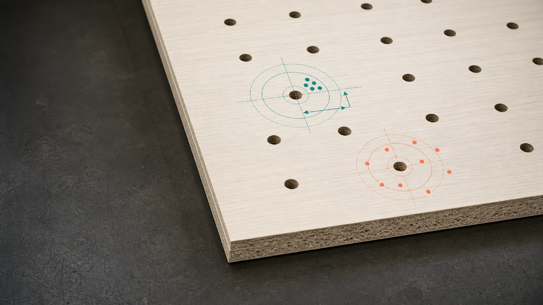 Measurement principle visualisation · not the station design
Drilling line setup and unit condition diagnostic assistant
Uses measured hole deviations to support faster line setup and early identification of worn drilling units.
Correct in X and Y directions
Scatter above the defined limit
Setup and unit diagnostics
Measurements from 4–5 parts can distinguish a systematic drilling head or unit offset from the scatter of results for the same hole.
Measurement logic
The operator and supervisor receive more than a table of points: they see where to look for the cause.
Actual hole positions are captured.
Results are compared across several parts.
Offset is separated from scatter.
A potentially unstable unit is indicated.
A setup action and direction are provided.
Product stage
In laboratory conditions, measurement repeatability of 0.04 mm was confirmed for the same part. Comparing 10 consecutively drilled parts produced a comparison of spindle scatter deviation. The first production installation is planned for September.
Faster, directed line setup.
A clear decision on what and where to correct.
A clear signal indicating which unit should be inspected, repaired or replaced.